
A reliable connection technology for copper, aluminum, and large conductor cross-sections
Today, electrical connections must do more than just be mechanically stable. Low electrical resistance, consistent quality, a compact design, and reliable process monitoring are also playing an increasingly important role.
Ultrasonic welding offers a unique solution for this: Wires and metallic components can be joined together in the solid state using pressure and mechanical vibration—without additional solder and, in the case of suitable direct wire connections, without a separate contact element.
This process is particularly useful for wiring harnesses, high-current connections, and high-voltage applications, as well as for connections between aluminum and copper conductors.
Key Points at a Glance
- The connection is formed by pressure and high-frequency mechanical vibrations.
- The base materials are not completely melted.
- For suitable applications, direct conductor-to-conductor or conductor-to-terminal connections are possible.
- Copper, aluminum, and coated conductors can be processed depending on the material and design.
- Energy, power, amplitude, displacement, force, and time can be used for process monitoring.
- The optimal welding time is not arbitrary: Welding times that are too short or too long can compromise the quality of the joint.
- For new combinations of materials and cross-sections, the process window should be determined through actual welding tests and then validated through appropriate inspections.
How does ultrasonic welding work?
In ultrasonic welding, the parts to be joined are positioned between the sonotrode and the anvil. A specified force presses the workpieces together while the sonotrode transmits a high-frequency mechanical vibration into the joint area.
The relative motion at the contact surface alters the surface structures and enables the formation of a metallic bond.
In this process, the material is not completely liquefied, as it is in conventional fusion welding. The joint is formed primarily in the solid state.
This process is particularly interesting for electrical conductors because it does not require any additional solder joints and, with proper design, can result in a large-area metallic contact zone.
For aluminum and copper conductors, particular attention must be paid to material combinations, surface condition, oxide layers, geometry, and process parameters.
Why is ultrasonic welding suitable for electrical conductors?
Low electrical resistance
An electrical connection should reliably transmit current while keeping additional power loss as low as possible.
In ultrasonic welding, electrical resistance depends, among other factors, on the material, the actual joint area, the surface condition, and the process parameters.
For this reason, electrical quality should not be evaluated based solely on a single resistance value. For a robust process qualification, the mean value, standard deviation, and behavior following temperature changes, aging, and electrical stress are all relevant.
Direct Connection of Conductors
One of the particular strengths of ultrasonic welding is its ability to join metal conductors directly to one another.
Depending on the application, the following connections, for example, can be made:
- Wire to Wire
- Conductor to Terminal
- Port to Port
- Splices
- High-Current Connections
- Connections Between Aluminum and Copper Conductors
Whether an additional contact element is required depends on the specific design.
Compact Connections
With the right geometries, an ultrasonic welded joint can be designed to be very compact.
This is particularly relevant for modern wiring harnesses and high-current applications, where installation space and weight are becoming increasingly important factors.
However, the actual achievable size depends on the conductor cross-section, conductor construction, weld area, and tool geometry.
Ultrasonic Welding of Aluminum and Copper
The increasing use of aluminum conductors is placing new demands on electrical connection technologies.
Aluminum offers advantages in terms of weight, but compared to copper, it has different mechanical and electrical properties and a distinct oxide layer.
In ultrasonic welding, the surface is affected by mechanical vibration. This allows the contact conditions in the joint zone to be altered, resulting in the formation of a metallic bond.
In the case of Cu-Al joints, the material combination poses particular challenges. In addition to the actual formation of the joint, potential intermetallic phases and their impact on the long-term quality of the joint must also be taken into account.
Therefore, parameters from another application should not simply be applied to a new Cu-Al combination. The material, cross-section, surface condition, and weld geometry determine the appropriate process window.
The Right Welding Time: Longer Isn't Necessarily Better
A common mistake in the development of an ultrasonic welding process is the assumption that a longer welding time automatically results in a better bond.
In fact, the joint goes through various stages of development during the welding process. As the welding time increases, the joint strength may initially rise significantly. However, once an optimal range is reached, further increases in welding time can lead to a deterioration in strength.
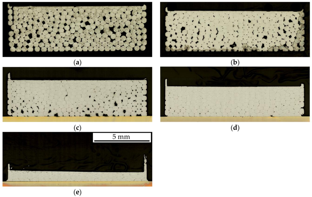
Figure: Metallographic cross-sections of welded joints in stranded conductors at different welding times: (a) 100 ms; (b) 500 ms; (c) 1,000 ms; (d) 1,500 ms; (e) 2,000 ms. Figure adapted from Gester, Ozherelkov, and Wagner, Metals (2024), © 2024 the original authors, used under the license CC BY 4.0, scaled.
In their process model for ultrasonic welding of aluminum and copper, Li and Balle describe „overwelding“ as a distinct phase that follows the improvement in joint strength.
Experimental studies of aluminum strands and copper terminals also show that the welding time has a decisive influence on the connection and the vibration behavior of the system.
For process development, this means:
The goal is not to achieve the maximum possible welding time, but rather a reproducible process window.
In this context, welding time, energy, amplitude, contact pressure, travel, and workpiece geometry must be considered together.
Vibrations as an Additional Indicator of the Welding Process
The quality of an ultrasonic weld depends directly on the mechanical vibration system.
These include, among other things:
- Generator
- Converter
- Booster
- Sonotrode
- Anvil
- Workpiece
If the contact or friction conditions change during welding, the system's vibration behavior may also change.
Gester et al. investigated the vibration behavior during the welding of aluminum strands to copper terminals using a laser Doppler vibrometer. After the optimal welding time was exceeded, sidebands in the range of the fundamental frequency and its harmonics were observed, among other phenomena. At the same time, increased slippage of the terminal on the anvil can affect the wear of the anvil structure.
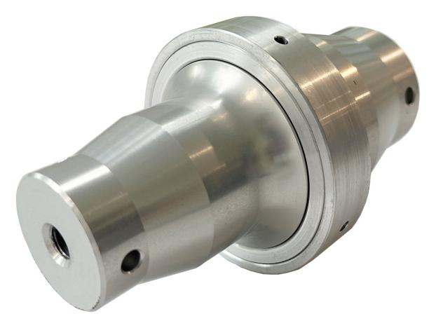
Figure: Magntek 20 kHz Booster
This makes it clear that:
In addition to welding time and energy, vibration behavior can also provide information about the current welding status.
For applications involving large cross-sections and high power, additional online vibration monitoring may therefore be worthwhile.
Process Monitoring: Each welding cycle can be evaluated
A key advantage of modern ultrasonic welding systems is the ability to collect process data during each individual welding cycle.
Depending on the system, the following parameters, for example, can be monitored:
- Welding time
- Energy
- Power
- Amplitude
- Path
- Strength
- Process Curves
This makes it possible to define process limits and detect deviations early on.
Recent research also shows that machine and sensor signals can be used for more than just traditional process monitoring. They can also be used to detect process states and assess connection quality.
However, one important limitation remains:
Process monitoring does not automatically constitute a non-destructive strength test.
To ensure reliable mass production, process data must therefore be combined with appropriate mechanical, electrical, and metallographic tests.
What types of testing are appropriate for ultrasonic welded joints?
The appropriate tests depend on the specific application and the customer's specifications.
Typical tests might include, for example:
Mechanical Testing
- Tensile Test
- Pull Test
- Shear Test
Electrical Testing
- Contact resistance
- Changes in Resistance Under Temperature Stress
- electrical load
Metallographic Testing
- Cross-section
- Evaluation of the Bonding Surface
- Investigation of Interfaces and Potential Defects
Aging and Environmental Testing
- Temperature Change
- Heat Aging
- Moisture exposure
- Vibration
- combined electrical and thermal load
A single test cannot fully reflect a connection's overall performance. For a reliable qualification, the test procedures and load profile must be appropriate for the intended application.
What factors determine the process window?
A stable ultrasonic welding process is not achieved through a single optimal parameter.
The key factor is the interplay of various influencing factors:
Material
Copper, aluminum, and coated conductors behave differently during welding.
Conductor Cross-Section and Conductor Construction
A solid conductor, a stranded wire, and a multi-layer conductor structure require different process conditions.
Surface condition
Oxide layers, coatings, contaminants, and insulation residues can affect the connection.
Amplitude
The amplitude determines the mechanical oscillatory motion in the joint zone and must be appropriate for the specific application.
Contact force
The force affects the contact between the joining partners and, consequently, the transmission of vibrations.
Energy and Sweat Time
The energy and time must be selected so that a sufficient bond is formed without compromising the bond due to over-welding or excessive material deformation.
Sonotrode and Anvil
Tool geometry and surface structure affect force transmission and the positioning of the conductors.
That is why a process window should always be developed using the actual production materials.
From the first prototype to mass production
A systematic development process is recommended for new combinations of conductors, materials, or cross-sections.
1. Define the application
First, the material, conductor cross-section, conductor structure, connection geometry, and desired connection type are specified.
2. Conduct welding tests
Using the actual conductors and connections, various combinations of amplitude, force, energy, and welding time are examined.
3. Determine the process window
The welding tests are evaluated for mechanical strength, electrical resistance, and, where applicable, metallographic properties.
4. Define Process Monitoring
Appropriate process variables and limit values are defined for mass production.
5. Validate the process
The connection is then qualified in accordance with the relevant standard, customer specifications, and the actual application profile.
This approach is particularly important when dealing with new material combinations. An existing set of parameters should not be applied to a different conductor cross-section or material combination without validation.
Magntek KS Series: Ultrasonic Welding for Various Conductor Cross-Sections
The Magntek KS Series includes four 20-kHz ultrasonic welding machines designed for various conductor cross-sections and joint types. Depending on the model, time and energy control options, as well as various machine and tool configurations, are available.
KSK is designed for precise connections in applications involving smaller conductor cross-sections and terminal connections.
KSM It features a compact design and is suitable for, among other things, through nodes and end nodes.
KSS It is designed for medium-sized conductor cross-sections and features a vertical wedge geometry with feed on both sides.
KSG It is designed as a high-performance dual-channel machine for large conductor cross-sections and, depending on the application, can create conductor-to-conductor, conductor-to-terminal, and terminal-to-terminal connections.
For new applications, it is generally recommended to conduct a welding test using the actual conductors and connections. Based on this, the machine configuration, tooling, and process parameters can be determined collaboratively.
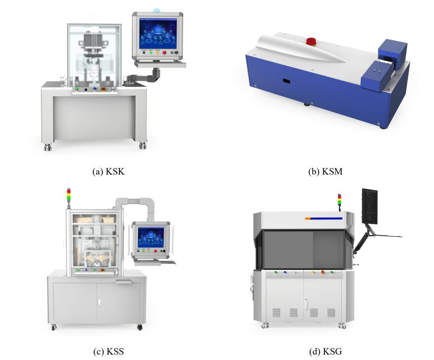
Figure: Magntek KS Series Ultrasonic Wire Harness Welding Machines
FAQ:
Do wires need to be stripped before ultrasonic welding?
Yes. In the actual welding area, the metal conductors must be free of insulation. Insulation residue can impair the connection and process stability.
Is solder required for ultrasonic welding?
No. In ultrasonic metal joining, the joint is formed directly between the metal parts being joined.
Does the conductor melt during ultrasonic welding?
The joint is formed in the solid state, without the base materials being completely melted.
Can aluminum and copper conductors be welded?
Yes. Both aluminum and copper can be ultrasonically welded for suitable applications. However, for different material combinations, the process parameters and the long-term joint quality must be validated separately.
Is ultrasonic welding suitable for high-voltage applications?
Ultrasonic welding can be used for high-current and high-voltage connections, provided that the material, cross-section, geometry, electrical load, and required tests are suitable for the specific application.
Is a longer welding time better?
No. A welding time that is too short can result in an inadequate bond. Conversely, a welding time that is too long can also be detrimental. The goal is a stable process window with reproducible bond quality.
Is it possible to monitor the quality of each weld spot?
Modern systems can collect various process data for each welding cycle and evaluate it based on defined thresholds. This improves traceability and process reliability, but does not automatically replace destructive testing and process validation.
Conclusion
Ultrasonic welding offers an effective way to join electrical conductors in the solid state. This process can provide technical advantages, particularly for direct conductor connections, splicing, and applications involving copper, aluminum, and high currents.
However, no single parameter is decisive. A stable joint is created through the interaction of material, conductor cross-section, surface condition, amplitude, force, energy, welding time, and tool geometry.
At the same time, the measurement of energy, power, displacement, force, and vibration behavior opens up new possibilities for continuous process monitoring.
For Magntek, this means that it is not just the welding machine itself that is crucial, but the interplay between the machine, the tool, the material, process development, and quality control.
Are you planning a new busbar or high-voltage connection?
You are welcome to provide us with your conductors and connection materials for a welding test. Magntek will assist you in selecting the appropriate machine, developing the process window, and evaluating the welded joint.
Sources and Further Information
[1] Li, J.; Balle, F.: „Process Model of Ultrasonic Welding of Aluminum and Copper.“ Welding in the World, 2026. DOI: 10.1007/s40194-026-02502-2.
[2] Gester, A.; Tetzner, A.; Wagner, G. et al.: „Development of a process monitoring method for ultrasonic metal welding of automotive wires based solely on machine sensor data.“ Welding in the World, Vol. 70, 2026, pp. 1123–1144. DOI: 10.1007/s40194-026-02346-w.
[3] Gester, A.; Ozherelkov, V.; Wagner, G. et al.: Investigations into the Ultrasonic Welding of Aluminum Strands and Copper Terminals. Metals, 2024. DOI: 10.3390/met14030362.
[4] Liu, J.; Cao, B.; Yang, J.: „Texture and Intermetallic Compounds of Cu/Al Dissimilar Joints Formed by High-Power Ultrasonic Welding.“ Journal of Manufacturing Processes, Vol. 76, 2022, pp. 34–45. DOI: 10.1016/j.jmapro.2022.02.001.
[5] Wu, X.; Liu, T.; Cai, W.: „Microstructure, welding mechanism, and failure of Al/Cu ultrasonic welds.“ Journal of Manufacturing Processes, Vol. 20, 2015, pp. 321–331. DOI: 10.1016/j.jmapro.2015.06.002.